- Juanma's Blog/
- Posts/
- Deploying OpenStack with KVM and VMware NSX - Part 2: Configure NSX Transport and Logical network views/
Deploying OpenStack with KVM and VMware NSX - Part 2: Configure NSX Transport and Logical network views
Table of Contents
Welcome to Part 2 of this series about OpenStack and NSX. In the first part we defined the basic NSX concepts and components, installed and configured the NSX appliances and connected the NSX Controller Cluster with the NSX Manager. In this second part we will see how Transport and Logical networks are configured, get yourself comfortable because this is going to be a long post :-)
To quickly refresh our concepts remember that the logical network represents the virtual machine point of view of the network and the transport network represents the underlying physical network through its transport nodes.
Configure the Transport Network #
The first step to have a fully functional NSX infrastructure is to configure the Transport Network. The Transport Network is made of the Transport Zone and the Transport Nodes. These transport nodes can be NSX appliances like Service Nodes or Gateways and hypervisors like KVM or ESXi hosts. Third-party hardware L2 Gateways can also be transport nodes but those are out of the scope of this series.
Create a Transport Zone #
A Transport Zone is a representation of the physical network used to to send traffic between OVS instances. Without a transport zone the transport nodes cannot be connected to NSX so it is mandatory that you define it before performing any operation on them.
Select Network Components -> Transport Layer -> Transport Zones.
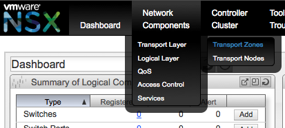
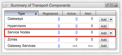
In the next screen click Add to launch the Create Transport Zone wizard. This same wizard can also be launched from the Dashboard screen in the Summary of Transport Components area click the Add button from the Zones row.
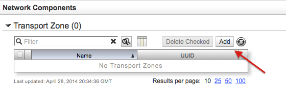
Enter the name of the Transport Zone and click Save & View.
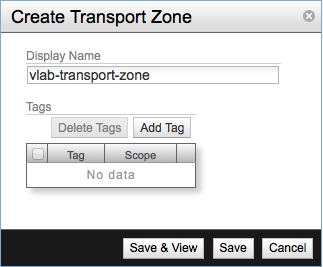
The new transport zone will now be available.
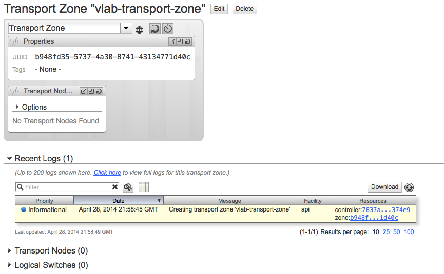
With the Transport Zone created we can start configuring the transport nodes.
Configure the Transport Nodes #
As we detailed in Part 1 the Service Node appliances are installed and configured independently as the rest of the appliances however they need to be added to NSX Controller Cluster in order to be able to perform the offloading function for the OVS devices.
From the Summary of Transport Components section in the Dashboard screen click Add.
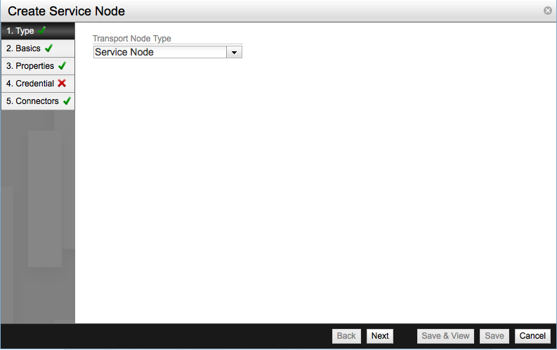
The Create Service Node window will show up. In the first screen select Service Node as the Transport Node Type and click Next.
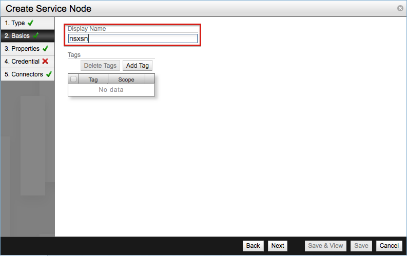
Enter the display name for the Service Node, in this case nsxsn.
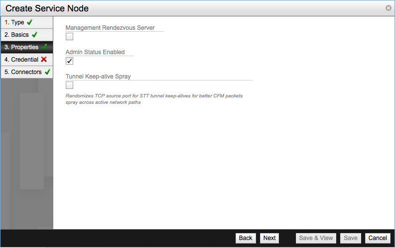
In the Properties screen you will see three settings available.
- Management Rendezvous Server - Used to designate the Service Node Management Rendezvous, it will proxy management traffic between NSX Controller Cluster and remote NSX Gateways.
- Admin Status Enabled - Used to enable or disable the Transport Node.
- Tunnel Keep Alive Spray - Used to improve the health testing of transport node’s tunnels.
For our lab leaving the default values will suffice.
For the next step get the SSL certificate from the Service Node. Establish an SSH session with the appliance as admin user and use the show switch certificate command. The output of the command can be a bit large, we just need the certificate itself.
-----BEGIN CERTIFICATE-----
MIIDgjCCAmoCAQMwDQYJKoZIhvcNAQEEBQAwgYExCzAJBgNVBAYTAlVTMQswCQYD
VQQIEwJDQTEVMBMGA1UEChMMT3BlbiB2U3dpdGNoMREwDwYDVQQLEwhzd2l0Y2hj
YTE7MDkGA1UEAxMyT1ZTIHN3aXRjaGNhIENBIENlcnRpZmljYXRlICgyMDE0IEFw
ciAyNyAyMzoyMDowNSkwHhcNMTQwNDI3MjMyMDUzWhcNMjQwNDI0MjMyMDUzWjCB
izELMAkGA1UEBhMCVVMxCzAJBgNVBAgTAkNBMRUwEwYDVQQKEwxPcGVuIHZTd2l0
Y2gxHzAdBgNVBAsTFk9wZW4gdlN3aXRjaCBjZXJ0aWZpZXIxNzA1BgNVBAMTLmNs
aWVudCBpZDpjYWIwNWU2OS1iZjI5LTRkMjItYTY1Ny0zYTJhZThkNjgyY2MwggEi
MA0GCSqGSIb3DQEBAQUAA4IBDwAwggEKAoIBAQC9lAk6DZWO/miggjjXk4xQd3hv
ieTPpjklw6Q4UKW+qMt0GjhC06n/cVK4kR12v1aCcxsKWmPK8LC1vU68e2T61zLe
NjRYHfa9VhqKjAY5p9xPcmQGli8+Cff47LfUVylEA+74YNMDHCuJbMagtwJOXSUa
UpaB3EnsEu6C4d4RzMBn55tlDbWAuFojH9JAki3g4maMqJRhILRUYoUFoSknmUvC
8cm719TcXw4u5cAzNBC2mMv6uRuDd+l1VquhFkksP2Di3D0/kI2yBW7lgDRTE4fn
O8hLasNPuGg24mOAkW/OIvusieW2MSqEwhGV5+G4fRgbRAI1ijTRT1K4dZuhAgMB
AAEwDQYJKoZIhvcNAQEEBQADggEBAB5bqYe2LXlIbwHSx1j28d/5FBmGxMd5LUEB
h29B+nTj3wVZkZpIxFoP/QRhzMXPWGM1PeixWN9o8oSZfrCEA7yMcn3uMMwdAmNz
7eNv4svw19hccWEvdNRBkQKdDX1YKItwUJKqVMJnI2dCqsGD4H1R9uwU+QJuEIgm
VMEoHYq7TwQXX6TR1eebjOKdeg4laOcsKystHTW+wuMBfOfcoYIuEZMQ7SOsRANe
l1hm3VI7t1gxp38r9JbtEC2jCqqBMzR+ZrzmodLsn/VgFDv8QiUZ5tFHaWl+jhQ/
JWxXqjLo42B6fRUA04wF6tJKnu3KDaVFIx4ssvKw2Q5u6PNSf8I=
-----END CERTIFICATE-----
Go back to the Create Service Node window and select Security Certificate as credential type and paste the certificate extracted from the Service Node in the Security Certificate text area.

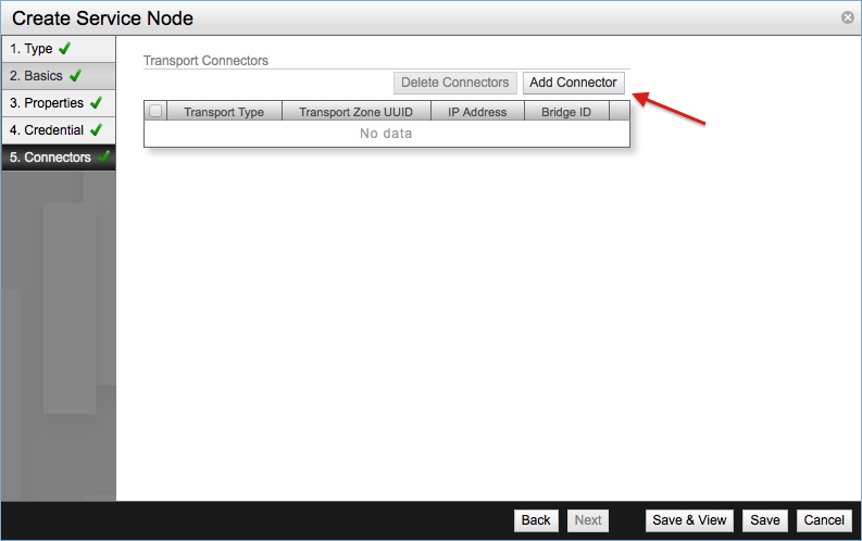
The final step is to setup the Transport Connectors. Click Add Connector.
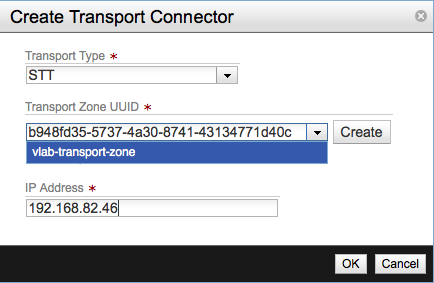
In the Create Transport Connector screen select STT as the Transport Type. Select the transport zone the we created before and enter the IP address of the Service Node.
Once the Connector is create click Save in the final screen and the new Service Node will be added to the NSX Controller.

Now we need to finish the Gateway appliance configuration in a similar way as we did with the Service Node. Again from the Dashboard and the Summary of Transport Components section, launch the Create Gateway by clicking the Add button in the Gateways row. The rest of the steps are very similar to the Service Node process.
- Select Gateway as Transport Node Type
- Get the SSL certificate from NSX Gateway with the
show switch certificatecommand. - Configure the credentials using the SSL certificate
- Create an STT Transport Connector and set the IP address of the Gateway
All the above Transport Node related tasks can be achieved through the command line by using the request transport-node-register command. This is a hidden command that can be used to register Service Nodes or Gateways in a NSX Controller Cluster. According to NSX documentation there are two versions of the command:
cert- Used for production environmentsmgmt-ip- Used for testing environments
The first one will transmit the encoded PEM certificates to the NSX Controller while the second will use the appliance management IP as the credential. The arguments for both versions are:
controller-ip-url- Switch manager address of the NSX Controller Cluster, accepts IP or hostname and the TCP port to connect to.ctrler-username- NSX administration account for the Controller.ctrler-password- NSX administration account password.mgmt-ip- The IP address of the transport node.cert- As we detailed before this one is exclusive ofmgmt-ipand viceversa.rendezvous-yes-or-no- Simply pass yes or no to indicate that the transport node is a Management Rendezvous Server one.tc-ip-address- IP address of the transport node connector.tc-zone.uuid- Transport Zone to be associated with the transport node.tc-type- Encapsulation format for the transport node’s transport connector.
With those arguments a registering command for our Service Node would be like this.
request transport-node-register nsxc.vlab.local admin admin mgmt-ip no tc-id 192.168.82.46 tc-uuid b948fd35-5737-4a30-8741-43134771d40c tc-type STT
Create a Gateway Service #
The next step would be to setup a Gateway Service. My lab lives within VMware Fusion and for now I don’t really need an L2 or L3 Gateway Service but since the purpose of this post is to illustrate NSX I decide to configure one and let everything in place for a future expansion of the lab.
Remember that Gateway services can be of two types:
- L2 Gateway Service - Will expand logical network by connecting it to a physical L2 segment.
- L3 Gateway Service - Connects virtual router ports to physical to physical IP networks.
It’s important to note that in an NSX deployment you may connect only one Gateway Service, either L2 or L3, to a given L2 physical segment.
L3 Service Setup #
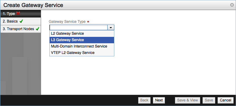
From NSX Manager Dashboard go to Summary of Transport Components section and in Gateway Services click Add. In the first step of the Create Gateway Service wizard select the L3 Gateway Service from the drop-down menu.
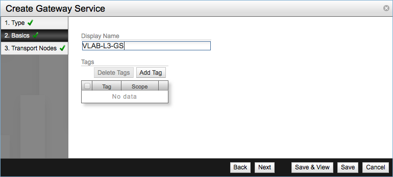
In the second step configure the Display Name for the new service and click Next.
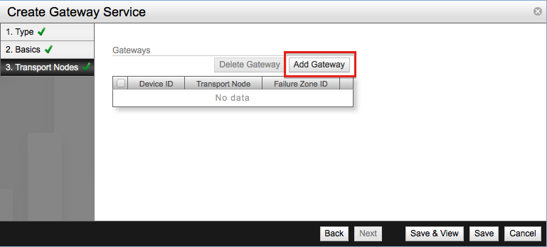
The third and final step is to bind our previously configured gateway node to the service. Click Add Gateway.
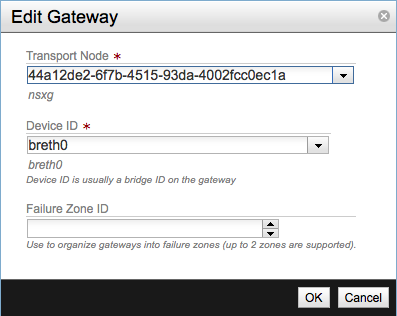
In the Edit Gateway pop-up select the UUID of the gateway node and the network interface to be used, leave the Failure Zone ID field blank. This last field is used for high availability of L3 services, I will try to write about this subject in a future post.
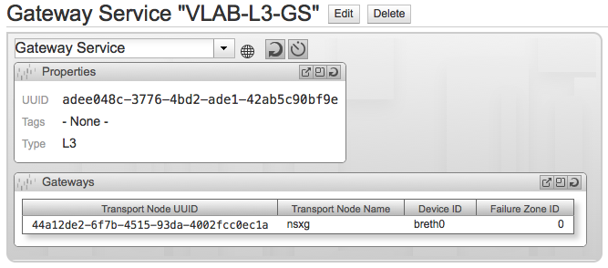
Click Save & View and check the newly created Gateway Service.
L2 Service Setup #
To create a new L2 Gateway Service follow the same procedure as with L3 one and launch the Create Gateway Service wizard.
- Select L2 Gateway Service.
- Enter the name of the new service.
- Add the gateway and fill in the UUID and network interface fields, this screen is slightly different since there is no Failure Zone ID field.
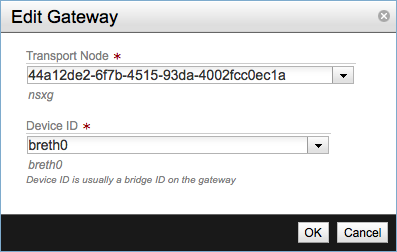
Please have in mind that the example of the above screenshot will fail because you cannot use the same gateway appliance for two different L2 or L3 Gateway Services, if you need an L2 service deploy a new gateway node and configure it following the above steps.
With this step our Transport Network is almost setup, the only part left would be to add the hypervisors to the Controller Cluster but I’ll left that part for the next article.
NSX Logical Network View #
In any typical OpenStack deployment the logical network elements will usually be created and configured not through the NSX Manager but NVP API. The API would be called by OpenStack Neutron module using the neutron plugin for VMware NSX either from Horizon dashboard or Neutron command line. However I decided to explain how to create and configure the different Logical Layer elements from NSX Manager.
Before starting with a simple walk-through of the process we need first to describe the different elements of the Logical Network. NSX Logical Network provide a similar functionality of a dedicated Ethernet switch. It recreates entities like switches, routers and ports and provides management functionality for them through NVP API.
- Logical Switch - Recreates an Ethernet-type L2 service-model, containing logical switch ports that can be configured to implement a set of security and QoS policies.
- Logical Router - Provides L3 routing services for the logical network. Can be configured to offer other services such as NAT and routed connections to the external physical network.
- Logical Switch Port - Represents and provides a logical connection point for virtual machines network interfaces (VIF), router patch connections or an L2 gateway connection to an external network.
- Logical Router Port - Provides the logical connection point for a patch connection to a switch or L3 gateway connections.
- Logical Port Attachment - This is the logical equivalent of connecting a network cable between an interface and a switch port.
Create a Logical Switch #
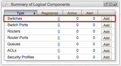
Let’s start from the begging and create a Logical Switch. From Summary of Logical Components and in the Dashboard screen click Add in the Switches row.
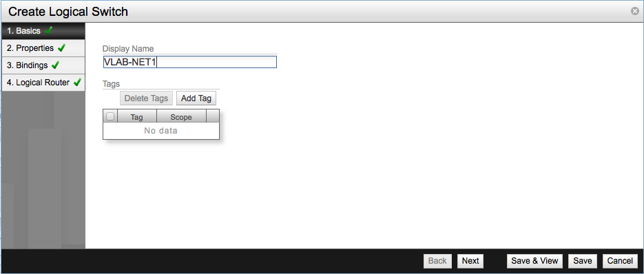
Provide the name of new switch and click Next.
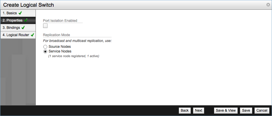
In Properties there are two different settings:
- Port Isolation Enabled - This setting basically disables VM to VM communication by preventing communication between the different logical ports of the switch.
- Replication Mode - Determines which transport node handle replication of broadcast, unknown-unicast and multicast (BUM) traffic. There are two possible values:
- Service Node - Traffic is sent to the NSX Service Node to be flooded to L2 logical segment. This is the default and recommended setting.
- Source Node - BUM traffic is handled directly by the source hypervisor instead of a Service Node.
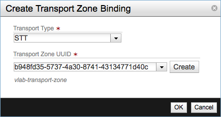
Next specify the transport binding for the logical switch. Click Add Binding and select the Transport Type and the Transport Zone UUID. I’ve selected STT our previously created transport zone respectively. For the transport type there are several types available:
- STT
- GRE
- Bridge
- IPsec GRE
- IPsec STT
- VXLAN
Click Save & View to review our new logical switch, leave the router connection for later.
Add Logical Switch Ports #
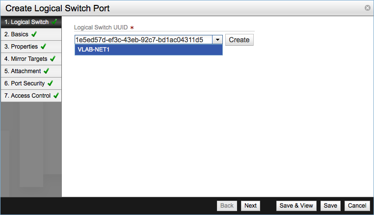
Once one or more logical switches have been created we can start adding ports to them. Ports will provide connection points to our virtual machines. Click Add in the Logical Ports row and the Create Logical Switch Port wizard will be started.
Select the Logical Switch the port will belong to.
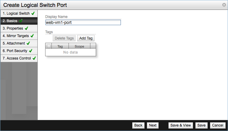
In Basics provide a descriptive name for the port, I tend to use the convention vm_name-port.
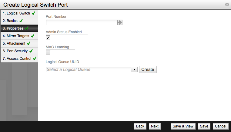
In the Properties screen you have the following filed available:
- Port number - Optional parameter.
- Admin Status Enabled - Enabled by default.
- Logical Queue UUID - An optional parameter used to link the port to a QOS policy.
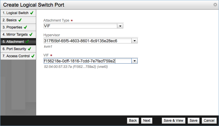
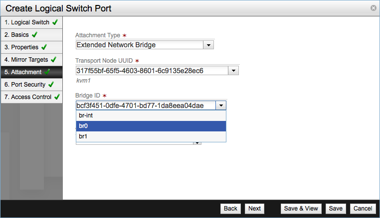
Leave the Mirror Targets settings with the default values and move forward to the Attachment screen. Select VIF, virtual machine interface, as Attachment Type, select a hypervisor and the network interface of the virtual machine.
Attachments can all be of type:
- None
- Extended Network Bridge
- Mult-Domain Interconnect
- L2 Gateway
- Patch to logical router port
- VTEP L2 Gateway
For example an Extended Network Bridged attachment should be configured like this.
Create a Logical Router #
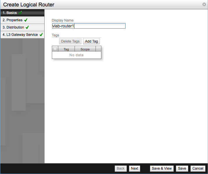
Launch the Create Logical Router dialog and set the name of the new router in the first screen.
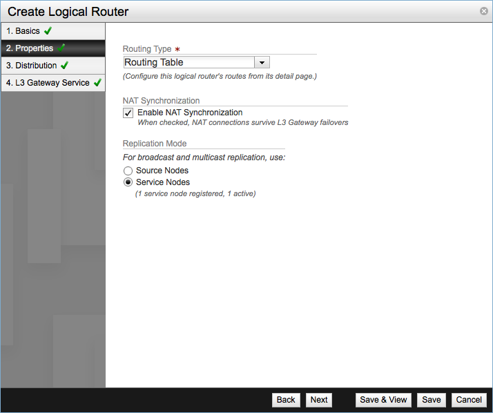
In Properties select the Routing Type:
- Routing Table - Allows to define static routes on the logical router
- Single Default Route - Defines a single default route for all traffic, routing all traffic through the L3 Gateway connecting the router to the datacenter physical network.
Tick Enable NAT Synchronization checkbox in order to provide NAT service through this logical router and want NAT rules to survive in the event of a Gateway failover.
Replication Mode works in the same way as in the Logical Switch, Service Node is selected by default.
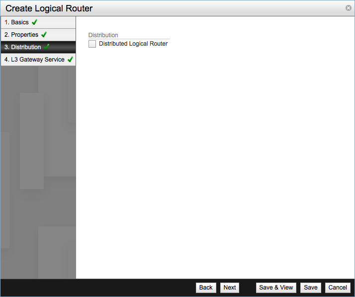
Configure the Distributed Logical Router. If the checkbox is un-ticked it means the logical router will be a centralized logical router and all network traffic between virtual machines will be forwarded to the NSX Service Nodes. On the contrary if you tick the checkbox it means it will be a distributed logical router and it will provide a one-hop routing of VM to VM traffic, to be able to use this feature all hypervisors running VMs using this router must be in the same transport zone.
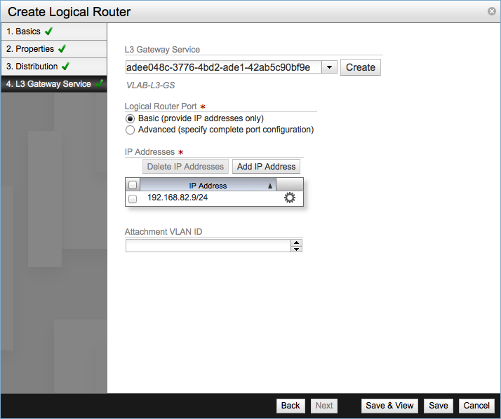
Click Save & View to finish the process and review the new router. Optionally at the last step you can assign an L3 Gateway Service and configure the corresponding Logical Router Port.
Select the UUID of the desired gateway service and configure the Logical Router Port settings. In the example I choose the basic configuration since I only need to provide the IP address for the port.
Add a Logical Router Port #
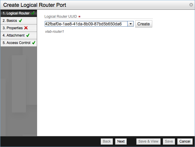
To create and assign a logical port to an existent router launch the corresponding wizard from Summary of Logical Components table in the Dashboard screen.
Select the Logical Router UUID from the drop-down.
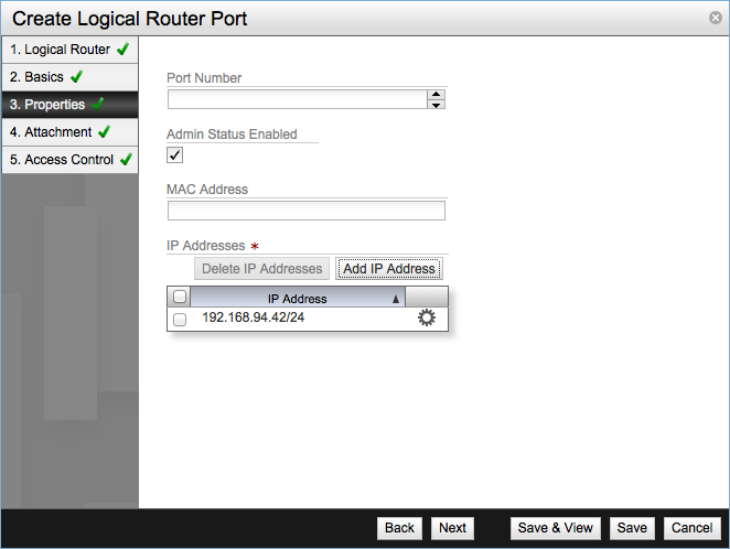
Enter a name for the port and click Next to move to Properties step. The Port Number and MAC Address fields are optional, leave Admin Status Enabled checked. In the IP Addresses table add the required IP address, must be in IPv4 CIDR notation.
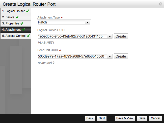
Configure the attachment. For router ports the attachments can be set to one of the following types:
- None
- L3 Gateway
- Patch
For my example lab this time I configured the attachment as a Patch one. You need to select the Logical Switch UUID and the Peer Port UUID, this peer port is port in the logical switch and you have to configure it either before creating the router port or you can create it at this step.
Click Save to finish the creation process.
This completes the logical network part, it’s a very basic setup without any security or QOS services but I hope that you gained a better understanding of transport and logical network concepts and the relationships between their different components. In third part of the series we will review how to setup the KVM hypervisor and connect it to the NSX infrastructure. Comments, corrections or questions are always welcome.
Juanma.